Finite State Machines
Table of contents
- Introduction
- Mealy state machine
- Moore state machine
- Interactive FSM
- Problem
- Rules
- Understanding the possibilities
- FSM diagram
Introduction
You know that synchronous sequential circuits change (affect) their states for every positive (or negative) transition of the clock signal based on the input. So, this behavior of synchronous sequential circuits can be represented in the graphical form and it is known as state diagram. A synchronous sequential circuit is also called as Finite state machine (FSM) if it has a finite number of states. There are two types of FSMs.
- Mealy State Machine
- Moore State Machine
Now, let us discuss these two state machines one by one.
Mealy state machine
A Finite State Machine is said to be Mealy state machine, if outputs depend on both present inputs & present states. The block diagram of Mealy state machine is shown in the following figure.
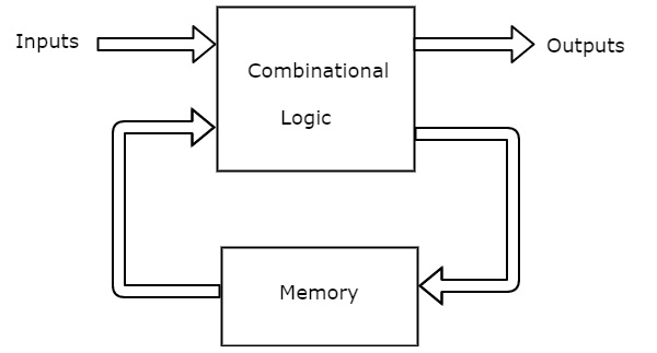
As shown in the figure, there are two parts present in Mealy state machine. Those are combinational logic and memory. Memory is useful to provide some or part of previous outputs (present states) as inputs of combinational logic.
So, based on the present inputs and present states, the Mealy state machine produces outputs. Therefore, the outputs will be valid only at the positive (or negative) transition of the clock signal.
The state diagram of Mealy state machine is shown in the following figure.
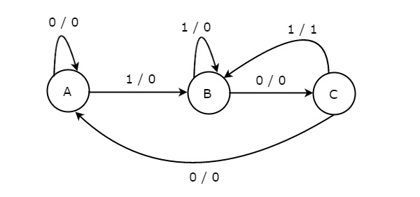
In the above figure, there are three states, namely A, B & C. These states are labelled inside the circles & each circle corresponds to one state. Transitions between these states are represented with directed lines. Here, 0 / 0, 1 / 0 & 1 / 1 denotes input / output. In the above figure, there are two transitions from each state based on the value of an input, x.
In general, the number of states required in Mealy state machine is less than or equal to the number of states required in the Moore state machine. There is an equivalent Moore state machine for each Mealy state machine.
Moore state machine
A Finite State Machine is said to be Moore state machine, if outputs depend only on present states. The block diagram of the Moore state machine is shown in the following figure.
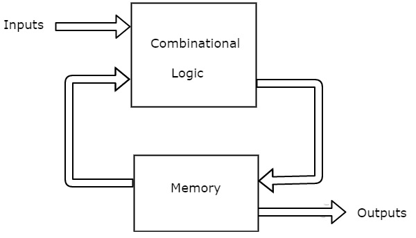
As shown in the figure, there are two parts present in Moore state machine. Those are combinational logic and memory. In this case, the present inputs and present states determine the next states. So, based on the next states, Moore state machine produces the outputs. Therefore, the outputs will be valid only after the transition of the state.
The state diagram of the Moore state machine is shown in the following figure.
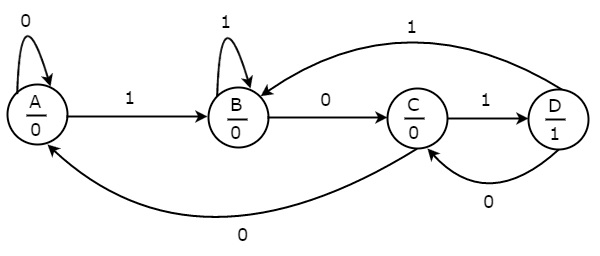
In the above figure, there are four states, namely A, B, C & D. These states and the respective outputs are labelled inside the circles. Here, only the input value is labelled on each transition. In the above figure, there are two transitions from each state based on the value of the input, x.
In general, the number of states required in Moore state machine is more than or equal to the number of states required in Mealy state machine. There is an equivalent Mealy state machine for each Moore state machine. So, based on the requirement you can use only one of them.
Interactive FSM
In this module, you will learn how to use a Final-State-Machine(FSM) which describes the working of a Soda vending machine:
Problem
Assume, you have a soda vending machine which sells soda cans of cost 15¢ each, and you have only 2 types of coins: 10¢ and 5¢.
In this problem, our goal is to make a state machine which can determine, how much change should be returned, and when a can is dispenced.
Note: In this design, ignore the capacity of the stock, which means, we’ll assume that there will always be can in the vending machine.
Also, you can assume that only one action could be made in every “clock cycle” or state.
Rules
- First, give the change.
- Then dispense the can.
Understanding the possibilities
There are quite some options like:
- entering no money.
- putting 5¢ followed by another 10¢ => getting the can.
- putting 10¢ followed by 10¢ => receiving change => getting a can.
- putting 5¢ followed by 5¢ followed by 10¢=> receiving change => getting a can.
- putting 10¢ followed by 5¢ and getting the can.
- putting 5$ followed by 5¢ followed by 5¢ => getting a can.
FSM diagram
Now translate the options which are listed above into an FSM diagram/flow-chart:
Lets try the soda can vending machine and look for the corresponding state changes FSM diagram in each of the above mentioned possibilities.