Logic gates
Table of contents
Introduction
Logic Gates are devices which perform logical operations on one or more inputs and produces a single output. Logic gates can be categorized into 3 groups:
- Basic Gates: NOT, AND, OR
- Universal Gates: NAND, NOR
- Arithmetic Gates: X-OR, X-NOR
Truth Table
The Table which contains all logical possibilities is known as truth table.
NOT gate
The NOT gate is also known as an inverter because it produces the exact opposite of the input as output. It has one input and one output. The Truth table for NOT gate is given below
| Input | Output |
|---|---|
| 0 | 1 |
| 1 | 0 |

Verilog code for NOT gate
module not_gate(
    input a,
    output c );
assign c=~a;
endmodule
AND gate
The AND gate’s operation is similar to that of multiplication. It has two inputs and one output. The output is high (1) if both inputs are 1, and for all other cases, the output is low (0). The Truth table for AND gate which consists of two inputs is given below
| Input 1 | Input 2 | Output |
|---|---|---|
| 0 | 0 | 0 |
| 0 | 1 | 0 |
| 1 | 0 | 0 |
| 1 | 1 | 1 |

Verilog code for AND gate
module and_gate(
    input a,
    input b,
    output c );
assign c=a & b;
endmodule
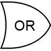
OR gate
The OR gate has two inputs and one output. If at least one of the inputs is 1, then the output will be high (1). If neither of the inputs is 1, then the output will be low (0). The Truth table of OR gate which consists of two inputs is given below
| Input 1 | Input 2 | Output |
|---|---|---|
| 0 | 0 | 0 |
| 0 | 1 | 1 |
| 1 | 0 | 1 |
| 1 | 1 | 1 |

Verilog code for OR gate
module or_gate(
    input a,
    input b,
    output c );
assign c=a | b;
endmodule
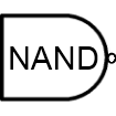
NAND gate
The NAND gate is the complement of the AND gate. You can think of it as an AND gate followed immediately by a NOT gate. Its output is low (0) when both the inputs are 1, and for all other cases, its output is high (1). The symbol of NAND gate consists of AND gate followed by a small circle. The Truth table of NAND gate which consists of two inputs is given below
| Input 1 | Input 2 | Output |
|---|---|---|
| 0 | 0 | 1 |
| 0 | 1 | 1 |
| 1 | 0 | 1 |
| 1 | 1 | 0 |

Verilog code for NAND gate
module nand_gate(
    input a,
    input b,
    output c );
assign c=~(a & b);
endmodule
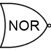
NOR gate
The NOR gate is the complement of the OR gate. You can think of it as an OR gate followed immediately by a NOT gate. Its output is low (0) when one or both of the inputs are 1, and for all other cases, its output is high (1). The symbol of NOR gate consists of OR gate followed by a small circle. The Truth table of NOR gate which consists of two inputs is given below
| Input 1 | Input 2 | Output |
|---|---|---|
| 0 | 0 | 1 |
| 0 | 1 | 0 |
| 1 | 0 | 0 |
| 1 | 1 | 0 |

Verilog code for NOR gate
module nor_gate(
    input a,
    input b,
    output c );
assign c=~(a | b);
endmodule
XOR gate
The XOR (or) Exclusive-OR is a digital Logic gate that gives the output as high (1) if and only if one of the input is 1. The Truth table of XOR gate which consists of two inputs is given below
| Input 1 | Input 2 | Output |
|---|---|---|
| 0 | 0 | 0 |
| 0 | 1 | 1 |
| 1 | 0 | 1 |
| 1 | 1 | 0 |

Verilog code for XOR gate
module xor_gate(
    input a,
    input b,
    output c );
assign c=a ^ b;
endmodule
XNOR gate
The XNOR (or) Exclusive-NOR is a digital Logic gate that gives the output as high (1) when both the inputs are same. The Truth table of XNOR gate which consists of two inputs is given below
| Input 1 | Input 2 | Output |
|---|---|---|
| 0 | 0 | 1 |
| 0 | 1 | 0 |
| 1 | 0 | 0 |
| 1 | 1 | 1 |

Verilog code for XNOR gate
module xnor_gate(
    input a,
    input b,
    output c );
assign c=~(a ^ b);
endmodule


You can also click/tap a symbol to copy it and then click/tap to paste it into the box.
Two-Way Light Switch
In your house you probabably have a light with more than one switch - e.g. landing lights often have switches upstairs and downstairs. Add the correct logic gate to the circuit and see if you can get this light work to work in the same way. You can click on Upstairs and Downstairs switches to change them.