Multiplexers and Demultiplexers
Table of contents
- Multiplexers
- Introduction
- Block diagram
- Multiplexers come in multiple variations
- Applications of Multiplexers
- Demultiplexers
- Introduction
- Demultiplexers in multiple variations.
- Applications of Demultiplexers
Multiplexers
Introduction
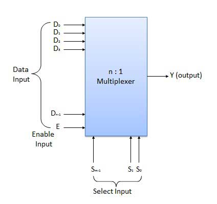
Multiplexer is a special type of combinational circuit. There are n-data inputs, one output and m select inputs with 2m = n. It is a digital circuit which selects one of the n data inputs and routes it to the output. The selection of one of the n inputs is done by the selected inputs. Depending on the digital code applied at the selected inputs, one out of n data sources is selected and transmitted to the single output Y. E is called the strobe or enable input which is useful for the cascading. It is generally an active low terminal that means it will perform the required operation when it is low.
Block diagram
Multiplexers come in multiple variations
2 : 1 multiplexer
Truth Table
Enable(E) = 1
| S1 | Y(Output) |
|---|---|
| 0 | T1 |
| 1 | T2 |
4 : 1 multiplexer
The 4 : 1 multiplexer has 4 inputs and 2 control signals.
Truth Table
Enable(E) = 1
| S1 | S2 | Y(Output) |
|---|---|---|
| 0 | 0 | T1 |
| 0 | 1 | T2 |
| 1 | 0 | T3 |
| 1 | 1 | T4 |
8 : 1 multiplexer
The 8 : 1 multiplexer has 8 inputs and 3 control signals.
Truth Table
Enable(E) = 1
| S1 | S2 | S3 | Y(Output) |
|---|---|---|---|
| 0 | 0 | 1 | T1 |
| 0 | 1 | 0 | T2 |
| 0 | 1 | 1 | T3 |
| 0 | 1 | 1 | T4 |
| 1 | 0 | 1 | T5 |
| 1 | 1 | 0 | T6 |
| 1 | 1 | 1 | T7 |
| 1 | 1 | 1 | T8 |
You can implement a 8 : 1 multiplexer by chaining two 4 : 1 multiplexers, like this:
16 : 1 multiplexer
The 16 : 1 multiplexer has 16 inputs and 4 control signals.
It can be implemented with two 8 : 1 multiplexers:
Truth Table
Enable(E) = 1
| A | B | C | D | Y(Output) |
|---|---|---|---|---|
| 0 | 0 | 0 | 0 | T1 |
| 0 | 0 | 0 | 1 | T2 |
| 0 | 0 | 1 | 0 | T3 |
| 0 | 0 | 1 | 1 | T4 |
| 0 | 1 | 0 | 0 | T5 |
| 0 | 1 | 0 | 1 | T6 |
| 0 | 1 | 1 | 0 | T7 |
| 0 | 1 | 1 | 1 | T8 |
| 1 | 0 | 0 | 0 | T9 |
| 1 | 0 | 0 | 1 | T10 |
| 1 | 0 | 1 | 0 | T11 |
| 1 | 0 | 1 | 1 | T12 |
| 1 | 1 | 0 | 0 | T13 |
| 1 | 1 | 0 | 1 | T14 |
| 1 | 1 | 1 | 0 | T15 |
| 1 | 1 | 1 | 1 | T16 |
It can also be implemented with five 4 : 1 multiplexers:
Applications of Multiplexers
-
Transmission from the Computer System of a Satellite - Multiplexer is used to transmit the data signals from the computer system of a spacecraft or a satellite to the ground system by using a GSM satellite.
-
Computer Memory - Multiplexers are used in computer memory to maintain a huge amount of memory in the computers, and also to reduce the number of copper lines required to connect the memory to other parts of the computer.
-
Telephone Network - In telephone networks, multiple audio signals are integrated on a single line of transmission with the help of a multiplexer.
Demultiplexers
Introduction
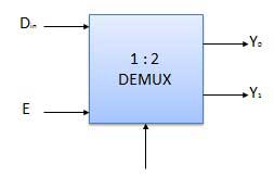
A demultiplexer performs the reverse operation of a multiplexer i.e. it receives one input and distributes it over several outputs. It has only one input, n outputs, m select input. At a time only one output line is selected by the select lines and the input is transmitted to the selected output line. A de-multiplexer is equivalent to a single pole multiple way switch as shown in fig.
Demultiplexers in multiple variations.
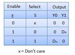
1 : 2 demultiplexer
Block diagram
Truth table
1 : 4 demultiplexer
1 : 8 demultiplexer
1 : 16 demultiplexer
A 1 : 16 demultiplexer can be implemented using two 1 : 8 demultiplexers.
Applications of Demultiplexers
-
Arithmetic Logic Unit - The output of the ALU is fed as an input to the De-multiplexer, and the output of the demultiplexer is connected to a multiple register. The output of the ALU can be stored in multiple registers.
-
Serial to Parallel Converter - In this technique, serial data is given as an input to the De-multiplexer at a regular interval, and a counter is attached to the demultiplexer at the control input to detect the data signal at the output of the demultiplexer. When all data signals are stored, the output of the demux can be read out in parallel.
- Which of the following directs data from input to a selected output line ?
- Demultiplexer
- Multiplexer
- Coder
- Both MUX & DEMUX
- Demultiplexer
-
Which of the following logic block has a number of input lines and one signle output line ?
- Decoder
- Multiplexer
- Demultiplexer
- Encoder
- Decoder
-
How many selection line will be there if a multiplexer has 8 input lines ?
- 1
- 2
- 3
- 4
-
How many output lines will be there in a demultiplexer if it has 3 selection lines ?
- 1
- 2
- 3
- 4
- 1