Encoders and Decoders
Table of contents
- Encoder
- Introduction
- Block diagram
- Priority encoder
- Block diagram
- Decimal to BCD encoder
- Octal to binary encoder
- Hexadecimal to binary encoder
- Decoder
- Introduction
- Block diagram
- 2-to-4 line decoder
- Block diagram
- Truth table
- Logic circuit
Encoder
Introduction
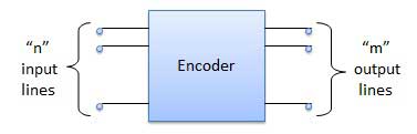
Encoder is a combinational circuit which is designed to perform the inverse operation of the decoder. An encoder has n number of input lines and m number of output lines. An encoder produces an m bit binary code corresponding to the digital input number. The encoder accepts an n input digital word and converts it into an m bit another digital word.
Block diagram
Examples of encoders ::
- Priority encoders
- Decimal to BCD encoder
- Octal to binary encoder
- Hexadecimal to binary encoder
Priority encoder
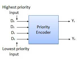
This is a special type of encoder. Priority is given to the input lines. If two or more input line are 1 at the same time, then the input line with highest priority will be considered. There are four input D0, D1, D2, D3 and two output Y0, Y1. Out of the four input D3 has the highest priority and D0 has the lowest priority. That means if D3 = 1 then Y1 Y1 = 11 irrespective of the other inputs. Similarly if D3 = 0 and D2 = 1 then Y1 Y0 = 10 irrespective of the other inputs.
Block diagram
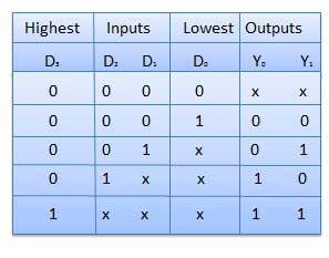
Truth table
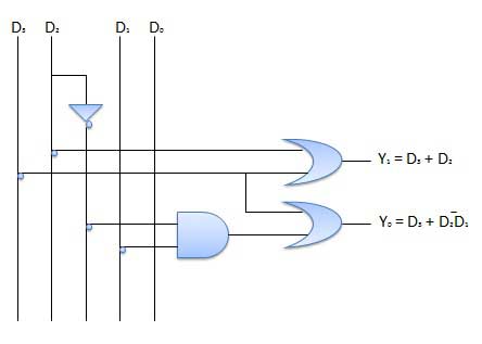
Logic circuit
Decimal to BCD encoder
The Decimal to Binary Encoder usually consists of 10 input lines and 4 output lines. The input is a number written in base 10 and the output is its corresponding equivalent binary coded decimal number (of 4 bits).
Octal to binary encoder
The Octal to Binary Encoder encoder usually consists of 8 inputs lines and 3 outputs lines. The input is a number written in base 8 and the output is its corresponding equivalent number in base 2.
Hexadecimal to binary encoder
The Hexadecimal to Binary Encoder encoder usually consists of 16 inputs lines and 3 outputs lines. The input is a number written in base 16 and the output is its corresponding equivalent number in base 2.
Decoder
Introduction
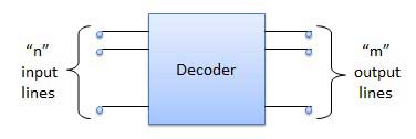
A decoder is a combinational circuit. It has n input and to a maximum m = 2n outputs. Decoder is identical to a demultiplexer without any data input. It performs operations which are exactly opposite to those of an encoder.
Block diagram
Examples of decoders ::
- Code converters
- BCD to seven segment decoders
- Nixie tube decoders
- Relay actuator
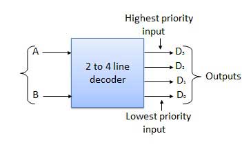
2-to-4 line decoder
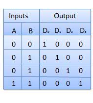
The block diagram of 2 to 4 line decoder is shown in the fig. A and B are the two inputs where D through D are the four outputs. Truth table explains the operations of a decoder. It shows that each output is 1 for only a specific combination of inputs.
Block diagram
Truth table
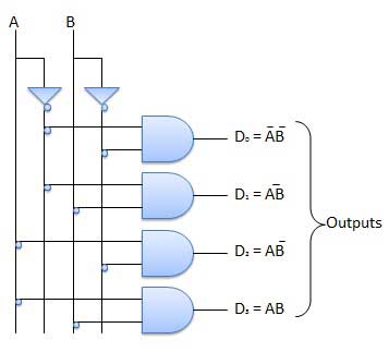
Logic circuit
- How many input lines exist in Decimal to BCD Encoder ?
- 4
- 10
- 8
- 2
- 4
- How many output lines exist in Decimal to BCD Encoder ?
- 1
- 4
- 3
- 2
- 1
- For conversion of BCD to seven segment display which of the following component will you use ?
- Encoder
- Decoder
- Comparator
- Multiplexer
- Encoder
- Identify the decoder IC ?
- 7890
- 8870
- 4047
- 4041
- 7890
- By using only which of the gates decoder can be formed ?
- AND
- OR
- NOT
- AND