Adders
Table of contents
- Half adder
- Introduction
- Block diagram
- Truth table
- Circuit diagram
- Half adder from universal gates
- Full adder
- Introduction
- Block diagram
- Truth table
- Circuit diagram
- Full adder from 2 half adder
- Full adder from universal gates
- Ripple carry adder
- Half subtractors
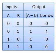
- Introduction
- Truth table
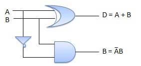
- Circuit diagram
- Half subtractor from universal gates
- Full subtractors
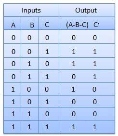
- Introduction
- Truth table
- Circuit diagram
- Full subtractor from universal gates
- N-Bit parallel adder and subtractor
- Introduction
- 4-bit parallel adder
- Block diagram
- N-bit parallel subtractor
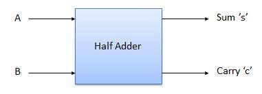
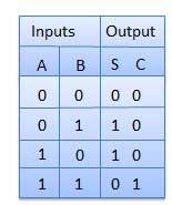
Half adder
Introduction
Half adder is a combinational logic circuit with two inputs and two outputs. The half adder circuit is designed to add two single bit binary number A and B. It is the basic building block for the addition of two single-bit numbers. This circuit has two outputs carry and sum.
Block diagram
Truth table
Circuit diagram
Half adder from universal gates
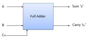
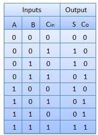
Full adder
Introduction
Full adder is developed to overcome the drawback of Half Adder circuit. It can add two one-bit numbers A and B, and carry c. The full adder is a three-input and two output combinational circuit.
Block diagram
Truth table
Circuit diagram
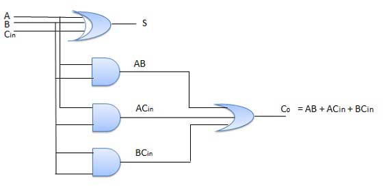
Full adder from 2 half adder
Full adder from universal gates
Ripple carry adder
Half subtractors
Introduction
Half subtractor is a combination circuit with two inputs and two outputs (difference and borrow). It produces the difference between the two binary bits at the input and also produces an output (Borrow) to indicate if a 1 has been borrowed. In the subtraction (A-B), A is called a Minuend bit and B is called a Subtrahend bit.
Truth table
Circuit diagram
Half subtractor from universal gates
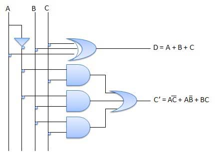
Full subtractors
Introduction
The disadvantage of a half subtractor is overcome by full subtractor. The full subtractor is a combinational circuit with three inputs A, B, C and two output D and C’. A is the ‘minuend’, B is ‘subtrahend’, C is the ‘borrow’ produced by the previous stage, D is the difference output and C’ is the borrow output.
Truth table
Circuit diagram
Full subtractor from universal gates
N-Bit parallel adder and subtractor
Introduction
The Full Adder is capable of adding only two single-digit binary number along with a carry input. But in practice, you need to add binary numbers which are much longer than just one bit. To add two n-bit binary numbers you need to use the n-bit parallel adder. It uses several full adders in cascade. The carry output of the previous full adder is connected to carry input of the next full adder.
4-bit parallel adder
In the block diagram, A0 and B0 represent the LSB of the four-bit words A and B.
Hence Full Adder-0 is the lowest stage. Hence its Cin has been permanently made 0. The rest of the connections are the same as those of n-bit parallel adder is shown in fig. The four-bit parallel adder is a very common logic circuit.
Block diagram

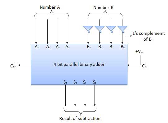
N-bit parallel subtractor
The subtraction can be carried out by taking the 1’s or 2’s complement of the number to be subtracted. For example, you can perform the subtraction (A-B) by adding either 1’s or 2’s complement of B to A. That means you can use a binary adder to perform the binary subtraction.
4-bit parallel subtractor
The number to be subtracted (B) is first passed through inverters to obtain its 1’s complement. The 4-bit adder then adds A and 2’s complement of B to produce the subtraction. S3 S2 S1 S0 represents the result of binary subtraction (A-B) and carry output Cout represents the polarity of the result. If A > B Cout = 0 and the result of binary form (A-B) then Cout = 1 and the result is in the 2’s complement form.
Block diagram
8-bit full adder and subtractor
- Consider a half adder circuit - for which of the following inputs A,B the sum (S) output is same ?
- 0,0
- 0,1
- 1,0
- 1,1
- 0,0
- Using only which of the following gates in minimum number Half Adder circuit can be implemented ?
- NOR
- AND
- OR
- NOT
- NOR
- Which of the following is 4-bit Full Adder IC ?
- 74LS83
- 7474
- 7408
- 7432
- 74LS83
- Which of the following circuit is called n-bit parallel adder ?
- Ripple Carry Adder
- Half Adder
- Half Substractor
- Full Adder
- Ripple Carry Adder
- In which of the following cases Adders can be used as a primary element ?
- Arithmatic Logic Unit (ALU)
- Digital Calculator
- Memory Block
- Loop Operation